Saturday, December 31, 2011

Medicine Cabinet for the Bathroom

At long last, the final item to be done for the downstairs bathroom remodel is a mirror / medicine cabinet to go above the sink.
I figured out a desired size, and stumbled on a beveled mirror at Goodwill for eight bucks.  It was two inches wider than what I  would have ordered from a glass shop, but i couldn't pass it up.  Here's what I made.


The final size is 33" high by 24" wide (not including the trim or wider base) by 4" deep.  Most of the case and the door frame is poplar, bought at bloody Home Depot as 3/4" stock.  I gotta quit doing that.  I could have made it from alder from rough stock from Crosscut for higher quality and less money, although this is a pretty small project.  The thick base piece, however, is a beautiful chunk of vertical grain douglas fir that I reclaimed from a 2 x 6 ceiling joist that came out of this bathroom when I did the demolition.  I shaped the little bullnose opening trim above the door with handplanes, and re-shaped the top trim from a stock shape with some creative sawing and gluing.  The polished nickel latch and 2" ball-tip hinges are from Rejuvenation Hardware.  It's overpriced, but they have what I want and I can see it before I buy it.  I feel like I should have gone with Horton Brasses though.  I used glass retainer clips with a little rubber bumper (from Rockler) to secure the mirror in the door rabbet.  I painted it with the same white semigloss acrylic wall paint I'm using for all the other cabinetry and trim in the bathroom, and I'll top it with a layer of paste wax after it's cured for a week or two.

Wednesday, December 21, 2011

A Parabolic Reflector

So, I want to play with a parabolic reflector to make a directional microphone, bit I don't want to spend a lot of money.  I can buy 1/32" polycarbonate sheets from TAP plastics, and maybe I could try forming that into a parabola.  I thought about just heating it and laying on top of a round trash can, letting gravity and maybe a small weight shape a curve.  Then I researched vacuum forming on the internet.  I think I could cobble something together...

There are instructions on the net for making parabolic microphones out of dollar store umbrellas, mixing bowls, and woks, but those aren't likely the right shape or size to really do the trick.  A parabola is a specific shape that reflects a set of incoming waves onto a point in the middle, so random bowl shapes won't necessarily give the concentration of sound energy I'm after.  The other issue is the size.  It takes a large reflector to deal with low frequency sound - an efficient reflector apparently needs to be twice as large as the sound's wavelength.  The speed of sound is about 1100 ft / sec, so a 2 ft diameter reflector is efficient to about 550 Hz, which is low enough for many wildlife sounds, and acceptable for human speech.  I also know that the $1200 Telinga parabolic mic that a lot of pros use is about 23", so mine will be one bigger.  Yeah.

For this purpose, a parabola is expressed mathematically by the equation:

y = x2 / 4f

where f is the height of the focus.  I wanted the focal point to be within the bowl of the parabola, so that sound from the sides would be blocked from the microphone element, and I wanted the diameter to be 24".  After testing a few values for f, I settled on 4.5.  That creates a parabola 8" deep, with a focus 4.5" from the bottom.


I calculated a y value for every half-inch from -12 to 12 (to make a 24" diameter dish), and plotted out the shape on a piece of construction paper, using a straightedge for the x axis and sliding a carpenter's square along it to measure up for the y axis.


I connected the dots, cut out the paper, and transferred the shape carefully to a piece of melamine-coated hardboard.  Then I cut the hardboard on the band saw and gave it a light hand sanding to make a smooth curve.  I might have been slightly more accurate to draw it directly on the hardboard, but I think my error was less than 1/32".

Next I cut a 26" diameter circle of 1/2" OSB sheathing with a router jig, and mounted a 8" long scrap of 4x4 to the center of it.  I carefully located the exact center, drilled a small hole in the top of the 4x4, and stuck a small finish nail in.  I cut the head of the nail off, leaving a small pin as a pivot point.  I drilled a mating hole in the center point of my hardboard pattern, and cut a notch in the outer part to ride on the edge of the circle.  Now sweeping it around on the pivot will form a 3D parabola.


Next I cut some rings out of a chunk of 1-1/2" foam insulation scrap.  I calculated the outer diameter at 1-1/2", 3", 4-1/2" and 6" high, and cut circles at that size.  I stacked them up, glued them together with some spray adhesive, and made a base for a plaster layer.  I trimmed the corners off to start rounding the shape.


I coated the foam layers with strips of fiberglass drywall reinforcement mesh tape.  It's a little sticky on one side, but I stapled the longer pieces to the wood block at the top and / or the wood base.  I used the pattern to make sure there was around 1/2" gap everywhere.  I also put a big lazy susan bearing under the wood base, which makes it much easier to work on.


Then I applied a layer of setting-type drywall compound to the form.  This stuff is basically plaster of paris with some fillers and retarders to slow the setting rate.  The type I used solidifies in 40 minutes after you add water.  Again, I was sure to leave this rough surface 1/8" - 1/4" low of the final finished height.  I let the whole thing dry out for a couple of days at this point.


Finally, I wiped a couple coats of Zinnser shellac on the hardboard pattern to waterproof it, and then used it as a screed to apply another coat of the setting compound.  The resulting surface has a few holes and defects, but is overall a very accurate shape.


After some filling and sanding, it's pretty smooth and I hope ready to use as a vacuum forming mold.

Update:  to my chagrin, I never got to test this mold out.  It turns out I'd have to build a big insulated box to make an oven to heat the polycarbonate sheet up, if I want to form it.  My original quick and dirty forming oven didn't have enough capacity.  I might do another one of these, in a size that I can just use our household oven to heat the plastic.  Don't tell my wife.

Monday, November 28, 2011

DeWalt DWP611 Mini Router Review

I got myself a new tool today.  My big Bosch router refused to start, I really needed to get some little hinge mortises cut, and I've been eyeing these little pint-sized routers for a while. This class of 1/4" collet routers has evolved over the past few years from the laminate trimmer category.

This one is really a miniaturized fixed-base router complete with all the features you'd expect.  The motor has a 7A rating, which probably means it's got enough power to drive any bit you'd find in a 1/4" shank. It also has a clear sub-base, variable speed control, and a pair of LED lights around the collet.  I played around with a few models in the store before buying this one at Lowe's for $119.  The LED lights and much smoother adjustment system sold it vs. the Bosch that was my second choice. It's made in Mexico, which is OK with me.

It's 3" in diameter at the grip (it's meant to be held in one hand at a textured metal grip near the base) and about 9" tall, although that changes depending on the depth setting. Depth is adjusted via a ring (marked in 1/64" increments) above the grip that engages threads in the motor housing.  Very fine adjustments are easy to make.  The height is locked with a cam buckle latch, or two tabs can be squeezed to quickly remove the motor from the base for bit changes.

So far I've just cut a few 1/16" deep hinge mortises in a pair of cabinet doors, so I can't speak to the power of this little tool, but I don't think that's the main selling point anyway.  I bought it for control over detailed cuts, and it did a great job balanced on the edge of a 3/4" workpiece without being wobbly.  Tomorrow I'll cut the matching hinge mortises in the face frame of my new bathroom cabinet, and I expect that to be pretty easy, too.

One-handed grip is good

Sunday, November 27, 2011

A desk light for the workbench

My woodworking bench has 3/4" dog holes for clamping work.  I made an adapter to fit those holes so I could install a swing-arm desk lamp.  It's really handy to get light right where I'm working, and I also use it to provide raking light when I'm planing or doing other surface work.


The adapter is simple.  I just took a 1/2" PVC  schedule 80 threaded nipple, filed the threads off until the end fit snugly into a dog hole, and then cut the end of the nipple off to leave a wide ring around the top.  The ring keeps the adapter bushing from falling entirely into the dog hole, and also holds the bottom of the lamp up off the bench so it doesn't drag and scratch.  Schedule 80 is usually dark gray, has a thicker wall, and the inside matched the diameter of the desk lamp post pretty closely.


Monday, November 21, 2011

My Thien Dust Collector

I wanted to upgrade my dust collection system.  I have a Jet DC-650 dust collector that I bought in 2003, with a good pleated filter on top, and a plastic bag on the bottom.  The filter is stock, and according to the particle counter I borrowed, it does a very good job of catching all the finest sub-micron dust.  However, I really hate emptying the bag, because it attaches with this sleek-looking but fiddly internal spring ring.  It takes a lot of bandsaw or table saw use to fill it up, but the planer especially will generate large amounts of big shavings.  I'd also like to have something between the blower and the intake because what happens if I accidentally suck up a larger chunk of wood or a nail?  Whang!  Into the impeller, and then it gets flung into the bag where it pokes a hole.

There are trash can lid separators, but they don't work well.  I made one of my own several years ago and ditched it pretty quick.  A cyclone separator would be good, but they're expensive and take up a lot of room.  Fortunately, a guy named J. Phil Thien came up with a pretty slick and simple dust separator that combines the functionality of a cyclone with the compact form of a trash can lid separator, and he put the idea up on the web for people to build for themselves.  What a guy!  I printed out a couple of pages from his website, and they've been sitting in my pile of shop papers for a few years.  Last week, I finally got around to building one.  I made it in a "top hat" style so that the separation happens in a separate unit above the trash can, and all of the volume in the can is available for debris.

I bought a quality 10 gallon metal trash can first, about 18" tall x 14" diameter at the top.  I had a couple of 16" x 15" pieces of 3/4" melamine particleboard left over from a shelving project, so those became the top and bottom plates, and I got a piece of 1/16" clear polycarbonate 8" x 48" custom cut from TAP plastics for $10.  Polycarbonate is flexible, and will stand up to impact a lot better than acrylic, so I chose it for the walls of the separator.  It's also nice to be able to watch the thing in action.  You could also use sheet metal, which would definitely be more abrasion resistant, but I don't think it will be a problem.  The inlet is a 4" plastic dust collection elbow, and the outlet is a 4" angled coupler.

I used a circle jig and router to do almost all of the shaping.  First I used a 1/2" bit to cut a dado in the bottom plate the same 14" diameter as the trash can, about 3/8" deep.  This fits over the rim of the can and holds the separator in place.  Then I used a 1/4" bit to cut slightly smaller diameter dadoes in both the top and bottom plates, about 1/4" deep.  This will hold the polycarbonate sheet I used for the sides.  Then I used the same 1/4" bit to plunge all the way through and cut the drop slot.  This slot is 1-1/4" wide, and goes 2/3 of the way around the circle of the lid.  I set the circumference so that the outer edge of the slot is about 1/16" inside the 1/4" groove for the sides so that the inside of the walls is flush with the outer edge of the slot.  I hope all that makes sense because I didn't stop to take photos.

Here is the groove to fit the trash can rim.  I've marked the ends of the drop slot.
I couldn't find my angle gauge, so I resorted to some late night trigonometry to figure out 120˚.
Too bad I didn't remember this trick.
Then I used a 4" hole saw to put a hole in the center of the top for the outlet, and another 4" hole in outer portion for the inlet.  I used three pieces of #10-24 threaded rod with nuts and washers to clamp the polycarbonate sheet in the grooves between the top and bottom plates, after putting a bead of caulk into the bottom groove.  I fastened the overlapping ends of the sheet by drilling holes and putting some #4x1/2" pan head screws through and into a strip of plywood.  I added a strip of self-adhesive rubber weatherstripping to the dado that mates the top to the trash can, because any little leak into the space below the drop slot plate is a big problem for this type of separator.

I hooked it up and the first thing I tried was cleaning out under my table saw.  I have a panel installed in the bottom of my contractor's type saw as part of the dust collection setup.  It accumulates a lot of dust and chips, and I stuck the hose in there and vacuumed it all up.  Just like a cyclone separator, it swirled against the clear sides in a downward spiral, and then dropped into the slot.  Pretty cool.  Only a layer of fine dust accumulated in the dust collector bag.  Here's a video.


Update:  I've been using it now for a couple of weeks, and it does just what I want it to do.  I've filled the trash can a couple of times and very little has made it to the dust collector bag.  I built this pretty fast, just to test the concept, and there are a couple of things I don't like.  The configuration requires a lot of elbows, which adds bulk, makes the hose fall off sometimes, and the inlet elbow inside causes a lot of turbulence.  I'm sure a side-inlet version would work a lot better, but I've got actual projects to deal with for now.

Thursday, November 10, 2011

Dust Hood for my Miter / Chop Saw

I take dust collection pretty seriously.  The fine particles are a health hazard, and it makes a mess anyway. So I've been rigging up ways to improve the dust collection of my tools over the years.  The chop saw makes a lot of dust, and it's tough to collect because it won't work with a bunch of shrouds and things near the blade.  I tacked together a very quick hood to help my dust collector capture most of what it generates.  After using it for a year, I think it works pretty well.  It's just three pieces of 1/8" lauan plywood tacked to a top and bottom trapezoid of 5/16" osb sheathing.  ie, I made it from scraps.  Dust collection is pretty effective.  With about 600 cfm of air being sucked into a port directly behind the blade, the fine dust gets captured pretty well.  Some bigger bits bounce off the hinge mechanism and are thrown around the room, but I'm less worried about that.  I've thought about making some kind of angled deflector to put on the saw to reduce that, but haven't got around to it.

Miter Saw Stand
I built it as a small rolling cart, with a bunch of storage below.  There are three small drawers in the top section, plus a flexible storage scheme I devised where sheets of hardboard slide in slots.  This makes very compact little drawers, perfect for bits and other small items.  The lower area has three larger drawers where I keep my cordless drills and small clamps.  Yeah, I've only put a front on one of the drawers and I'm using screws as handles.  I'm classy.
Storage Below 
I attached a plastic dust collector fitting at the bottom of the dust hood, then a short length of 4" hose, with a quick-connect on the end.  I attach the hose from my dust collector to each machine as I use it for maximum airflow.  I tacked a piece of plastic gutter screen over the opening to keep from losing chunks of wood and other large debris down the pipe.
Dust Collection


Thursday, October 13, 2011

Building a Gate That Won't Sag

Here's a plan for a simple gate.  I've built two of these for my own yard, and one larger one for a neighbor. Despite his kids occasionally climbing on it, it has held up very well.  No special hardware or fussy joinery.  Just a couple of miter cuts and a little analysis of the physics of gates.

Cedar Gate in my yard

If you just attached two pieces of wood at a right angle, one vertical (a stile) and one horizontal (a rail), and put hinges on the stile, the rail can swing back and forth as a very simple gate.  It probably won't last too long, because all the weight of the rail is trying to twist the joint apart.


By installing a support at an angle between the base of the stile and the far end of the rail, you form a triangle, which is a very stable shape.  The weight of the rail is now supported by the angled brace and the top of the stile, and there are no forces acting to twist the rail-stile joint and cause the gate to sag.

You could theoretically get the same behavior from an inverted version, where the rail is low and the diagonal brace runs from the top of the stile down to the end of the rail, but now the ends of the brace are under tension.  Without special joinery (or welded metal fabrication) the parts will tend to separate.

So take that triangle and hang whatever kind of decorative stuff you'd like to on it.  In my version, I start with two rails, about 1/2" narrower than the opening you're putting the gate into.  Put them far enough apart that the brace runs at a 45˚ angle or higher with respect to the ground.  A short, wide gate is under much more strain than a tall narrow gate.  If the opening is very wide, you might consider a double gate, with one on each post and the latch in the center, but those have their own problems.
You can see how the wooden components form the rail, stile, and support from the diagram above.  When I build mine, I just put screws through the decorative pickets into the rails and support.  I don't actually join the support to the rail, and there is no framing member to form the stile, since the pickets serve that function.

Monday, October 3, 2011

Cleaning Paintbrushes with a Fork

After using a brush with water-based paint, I've found that the quickest, best way to clean the brush is with a fork.  Run a stream of water over the bristles while combing them with the tines of a regular dinner fork.  The tines split apart the gummy paint that accumulates up higher in the brush, and lets the water quickly penetrate into the bristles so the paint rinses out quickly and thoroughly. 
Once the water runs clear, give the brush a good shake to get rid of most of the water (I like to do this outside over the lawn), smooth the bristles into their proper shape, and leave it to air dry.

Thursday, June 9, 2011

Bench Planter III: Seating

I had intended to buy bluestone (sandstone), basalt, or some other nice masonry product for the top seating surface of the wall, but Jackie was intent on using some sort of composite decking material, like we used on our back steps.  Stone would have been much easier in some ways.  Mix up some mortar and plop it down...  But since the surface was going to be about 12" wide on top of a 6" wall, there would be some cantilever forces to deal with, and mortar isn't the greatest for that.

After several evenings of head scratching, here's what I came up with.  It's simple, strong, and removable if we change our mind or damage it.  First off, I mixed up a small batch of mortar and put a smooth coat on the top of the wall, pitching it very slightly so water wouldn't pool and (especially) have cracks to freeze in and damage the masonry.

We had to drive to Tualatin to pick up three 16' lengths of gray composite decking, because stupid Home Depot quit stocking the stuff I bought from them for the back steps.  I cut them down to 12'-3" and saved the offcuts to build the sides.  The front bench was made from three pieces, two 5" and one 2-1/2" in the center.  I ripped 1-3/8" off either side of the 5-3/8" stock for the center piece, and ripped a little 3/8" ribbon off one side of the other two to get the 5" pieces, because I wanted to get rid of the rounded edges in the middle of the seat.  Ripping them was a challenge I solved by building an oversized plywood sub-base for my circular saw and clamping a scrap fence to that.

Then I cut 11" sleepers from pressure treated 2x4, fastening them at the ends and every 16" along the front of the wall with 1/4" x 2-3/4" flat-head Tapcon screws.  Some sleepers got two fasteners to resist the cantilever forces.  I've never been a fan of Tapcons.  They seem like they're made more for the contractor who wants to get it done in a hurry than for people like me, but they do work and I'm installing a lot of fasteners so if one fails it's no big deal.  I've also got more experience working with concrete anchors and have learned the importance of drilling a little deeper and especially of cleaning out the anchor hole.  Concrete dust isn't like wood dust.  It doesn't compact past a certain point, and if you leave any in the bottom of a hole, it can cause the fastener to seize up, so brush & blow out big holes with an air gun, or at least run the drill bit in and out a few times to extract most of the excess.  The 3/16" holes go pretty fast with my big Bosch rotary hammer.  I also am now the proud owner of a small impact driver (I got a Milwaukie drill / impact driver set last year), which makes driving these puppies a piece of cake.  Install a #3 phillips bit into the driver and put on your hearing protection!  Bbbbbbbbbbbbbt.  Done.

Use a mason line to get them all lined up
The decking was fastened to the sleepers with #7 x 2-1/2" stainless steel finish screws, pre-drilled and countersunk, of course.  I left a minimal 3/32" gap between the decking, to keep the appearance neat and easy to clean.
Shorter sleepers on the sides
The sides were built in a similar way, but with a narrower surface made from 5" wide and 2-1/4" wide pieces.  Three 6" sleepers were installed on each side, and one of the 3'-9" offcuts was ripped in half to make the narrow strip.  I used the long 1-3/8" strips to trim around the lower edge of the seat, hiding the sleepers.  It doesn't look perfect from all directions, because the ends of the decking show the ribbed bottom, but it's very solid and should hold up well to the elements.
the finished seating surface
I think an idea that would have been more fun would have been to cast our own concrete pieces, like building a concrete kitchen countertop.  With the right reinforcing and some cast-in attachment hardware, it would have been strong and stable, and we could have stained it whatever color we liked, or put a cast or embedded design in it.  Maybe next time!

Wednesday, June 8, 2011

Bench Planter II: Carpentry

A few days after building the wall, when all the structural masonry had some time to cure, we started on the rest of the construction.  My plan was to use two pressure-treated 2 x 10 timbers to build the back wall, supported by three 4 x 4 posts that would extend up to support a trellis.  I dug three post holes, 20" deep, for the three 4 x 4 x 10' trellis posts; one behind each end of the wall, and one in the middle of the bed.

Four 3/8" x 6" galvanized lag screws were used on each side to attach through the posts into the masonry, sandwiching the 2 x 10's.  I countersunk the heads of the lag screws 1-1/2" into the posts with a 1-1/8" forstner bit so that they'd be hidden and also so that the 6" screws would penetrate far enough into the masonry wall.  We held everything in place while I used a long wood bit to drill through the posts and boards, and then a 1/2" bit in the hammer drill to reach through and start holes in the concrete before removing the wood temporarily.  I used a hammer drill to install eight lag shield anchors into 2-1/2" x 5/8" holes in the back before fastening everything with the lag bolts.  The post holes were backfilled with packed soil, instead of pouring a concrete footing.  Everything feels extremely solid, but shouldn't be a nightmare to take apart if we need to for some reason.


We immediately went and got a yard of compost mix and filled the planter up.  I'm not sure that was a good idea, but I guess, worst case, we shovel it all out some time and adjust the structure.  The main thing I'm worried about is the wood back.  I think there should have been a plastic sheet liner installed between it and the soil.  It would help the wood last longer (even p.t. eventually rots), it would keep nasty preservatives from leaching into the planter's soil, and it would keep the soil at the back of the planter from drying out.  The drying issue may be a problem against the concrete, too.

Bench Planter Construction I : Masonry

After deciding for sure on a location and size, and testing out the plan by stacking up some blocks, we started by digging a shallow (6") trench for a poured concrete foundation.  I built forms from 2x4 material that were exactly the outside dimensions of the finished wall, and we filled them with 12 bags of concrete, sticking pieces of rebar in at some locations where the web holes in the block would be.
Ready for concrete
This isn't a "real" foundation, like you'd build for a house or other serious structure.  It doesn't go deep enough, and doesn't have enough rebar, but I think it will be fine for this project.

The finished foundation
The next day, I mixed up a bag of type-S mortar and built the wall from 6 x 8 x 16 concrete blocks.  I'd carefully laid out the orientation and spacing before even digging the foundation, so it went pretty quick.  Basically I just buttered everything up with mortar, set a block in place, and tapped it into position with a chunk of 2x4 until it was level and plumb, being especially careful with the corners and ends.  I scraped off any squeeze out as I went, and used it for the next block.

All mortared together
We then filled some of the empty cavities with concrete (all the re-bar containing ones and a few others in structural spots) and filled any gaps with mortar.

Filling the cells
Jackie then applied a skim coat of mortar to the entire outside face, and textured it with a plastic broom so that it matches the texture of our house's foundation.
Mortaring in the dark

Using a template to cut shapes with a router

This is just a quick how-to on a technique I use to quickly cut shapes in wood.  I've used it for decorative shapes on outdoor projects and curved legs on furniture, among other things.  It's really a time saver when you need to make several of the same shape, and you can keep the templates and use the curves on other projects down the road.  I just re-used a template I made several years ago (for a garden arbor) to cut decorative ends on the cedar beam across the top of a trellis structure.

1.  Make the shape.  I usually draw the shape at full scale on a piece of graph paper, or sometimes with software, and print it out.  Sketchup (free and excellent) or Adobe Illustrator (expensive but powerful) can both be used to make all sorts of curves.  Pencils work pretty well, too.
A template design I made in Illustrator
2.  Cut the template.  Plywood or hardboard is best for this, and 1/4" to 1/2" thick is good, depending on the size of the  part.  You do need to plan ahead a bit here.  If you're going to clamp the template to the stock to be cut, you should make it big enough that the clamps don't get in the way of the router.  I tend to cut a piece of plywood the same dimensions as the stock lumber, and then about a foot longer than the cutting area will be.  Transfer the pattern you drew to the plywood, and cut out the curve with a band saw, jig saw, or coping saw.  A quick way to do this is to use spray adhesive to glue the paper down.  Cut a little outside of the line, and then finish the curve with a sanding drum.  There are cheap sets you can get to go in a hand drill or drill press, or you can invest in a dedicated oscillating sander.  One tip:  larger drums make smoother curves, so don't try to smooth out a 10" long shape with a 3/4" diameter sander.  Take your time and make sure the template is fair and smooth, because every bump will be faithfully transferred to your final work.

Trace the pattern first
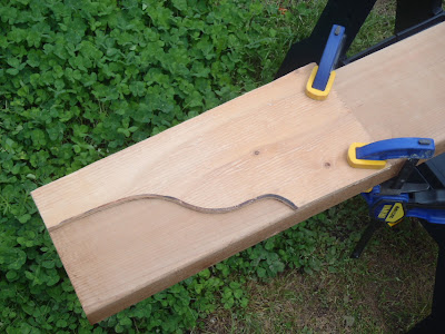
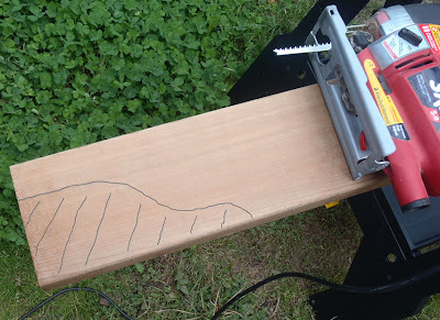
3.  Prepare the workpiece.  You should rough-cut the curve with a bandsaw or jigsaw, within 1/4" of the line.  I usually just hold down the template, and trace it quickly with a pencil.  I also make hash marks on the waste side, which seems silly until you accidentally cut on the wrong side of the line because you got in a hurry.  You could skip right to step four, and do all the cutting with the router, but your results will be much better and your router and bit will be much happier if you're not hogging out huge amounts of wood.  If you're using a small router, this is a mandatory step.

Hash marks on the waste side prevent expensive mistakes
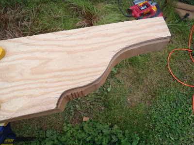
4.  Attach the template to your workpiece.  I usually just clamp the template in position.  If some small holes are something that can be dealt with, sometimes it's good to use a couple of small #4 or #6 flat-head screws countersunk into the template.  The router base can run right over them, and they can be used to fasten in the middle of a large or odd-shaped piece.  When deciding how to attach the template, consider the cutting direction of the router bit.  You want it to be working with the grain of the wood as much as possible, to avoid chattering and splitting.

Ready for the router

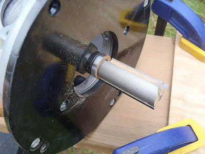
5.  Cut it!  My weapon of choice for this one is a 3/4" diameter x 2" template cutting bit with a bearing at the top (Whiteside #3023) in a fixed-base router.  Set the height so that the bearing runs along the template and watch the bearing as you cut, not the cutter.  Again, watch the grain direction and try to cut with it.  You might need to climb cut around some curves, which is no big deal if you pre-cut the shape fairly closely.
A big bit gets the job done easily
Ta-da!  I usually leave the edges crisp and smooth from the router, but a quick pass with a roundover bit or hand sanding will make a smooth edge if you want.  Otherwise, there's no more woodwork required.

No sanding required

Tuesday, May 24, 2011

Metal Trough Planters

A couple of years ago, I ran into a woman who was asking how she could get rid of some black bamboo (Phyllostachys nigra) that she'd planted in her yard.  She'd cut it down one year, and it had all sprouted back up.  I perked up because I was at a sale shopping for bamboo when she said it, so we went over and dug up several clumps and cleaned up her patch in trade for about $150 worth of free bamboo.

We planted it in the ground, in big rubbermaid containers with the bottoms cut out, because that was my strategy for preventing escape.  18 months later, and we were ready to completely re-do the yard in that area.  The bamboo came out, we built a new fence behind it, and put it back in the same spot, but this time, in above-ground planters that are sold as livestock watering troughs.  They're heavy galvanized sheet metal, with a handy drain hole and a rolled rim.

This is not a new idea.  We see these planters all the time, but here's what it looked like when we did it.

First off, we leveled off the area, and packed the dirt with a tamper to try to reduce any later settling.  Then I went and picked up a half yard of 3/4-minus crushed rock, and we put down a couple of inches of that, tamping as we went.  The tamping is very important, if you don't want the ground to subside on its own later and ruin your work.  I use a hand tamper that is basically a ten-inch square of cast iron with a handle.  It weighs about 15 lbs, and it's a good workout.  You can also make your own out of wood, or just use a chunk of 4x4 for small jobs.  It's amazing how solid a bed of crushed rock gets after compaction.  The fine bits fill in the gaps between the bigger chunks, and it makes for a very sturdy surface.  Stomping with your boots isn't really a substitute, because you need to deal more of a blow than your feet can handle.


We set the troughs in place, and made sure they were level with each other and sat nice and flat.   It took a few iterations of wiggling the planters, and then removing them and adding rock and raking and tamping, but this is the only chance to get it right.  Once we were happy with the position, we put a bit of rock in the bottom for drainage, and then filled the first foot with fill dirt (very little organic material), and then topped it off with about 16 inches of mixed compost and soil.  Our neighbor helped us heave the giant bamboo root balls into the planters and that was that.


A few weeks later, several new canes have sprouted.  Hopefully, if I can keep the sun from roasting the containers, the bamboo will be happy here and provide a nice backdrop for the yard.

New Back Fence

I came up with this fence design in 2005, and building it was the first project we did when we moved into our house.  I wanted it to look good from both sides, and of course be reasonably solid.  It's basically a set of horizontal rails that are used to sandwich the pickets.  For a six ft. tall fence, I use three pairs of rails; 1x6 at the bottom, 1x4 in the middle, and 1x2 at the top.  The rail configuration and picket width and spacing can be varied to change the style of the fence with little effort.  Everything is held together with screws, which means it's pretty easy to take apart and repair or modify, and pre-drilling every hole means no splitting.  The panels are held to the posts by custom-made aluminum brackets, which are strong and non-corroding, while being invisible from one side and low profile from the other.

For the design I'm building here, the pickets alternate between full-width (5-1/2") and 1/3 width (1-3/4") and have a 3/4" gap between each one.  I like this layout for fences that don't require the most privacy, and it makes a better wind screen than a solid fence.  Yes, the gaps improve the wind performance.  Go ask a physicist why.

So here's a step-by-step guide:

1. Set the posts.  We have relatively solid clayey soils, so a simple protocol of digging a small hole and setting the post in concrete is plenty.  I set an 8 ft. 4x4 (either pressure treated or quality cedar) about 21 in. down.  That leaves 6'-3" above grade, enough for the post tops to rise an inch or two above the top of the fence panels.  I always install the two corner posts first, let them set up, and then stretch a piece of mason line between them so that I can line up the remaining posts to that reference.  No need to fill the hole right to the top.  Even if you skip the curb (next step) you don't want to look at the top of a concrete plug around each post, so leave the surface a few inches below grade.  Do slope the top of the concrete away from the post, however, to prevent water from pooling against the wood.

2.  Pour a short concrete curb at the base.  We just did this for the latest rendition of the fence across our north property line, but I'm going to go back and add this feature to some of the other segments.  It prevents weeds and animals from crawling under, keeps the lowest wooden parts of the fence away from the soil, and makes for a much neater appearance.  Plus it's easy and cheap.  Scrape off three or four inches of soil (frost concerns are minimal to nonexistent here) and build forms by simply screwing 2x3's on each side of the posts.  I put the tops about 2" above finished grade, and the bottom about 2" below.  Make sure they're level across the width, and you can make them level or at a slight angle to follow ground contours between the posts.  Mound soil along the outside of the forms to keep them from bowing out when you pour the concrete in.

Filled and screeded flat.  Note the water that floats to the surface.  Do not disturb at this stage.


When you fill the forms, work it into all the corners and vibrate it a bit by hand to get the bubbles out.  Then just screed it flat by sawing back and forth with a scrap of lumber.  A layer of water will appear at the surface, and then disappear after 30 minutes or so.  At that point, the setting process should be far enough along that you can put nice curved edges on the top of the pour with an edging tool; just run it back and forth for a much improved final product.  Unscrew the forms and rap them gently with a hammer to knock them loose after at least several hours.

Time to remove the forms

 3.  Make and install the aluminum brackets.  I start with aluminum angle, 1"x1"x 1/6" thick.  You'll need one for each end at each set of rails, and I cut them a little shorter than the rail material.  So, 2 ea. 1-1/4", 2 ea.  3-1/4", and 2 ea. 5-1/4".  Drill two screw clearance holes (just one on the 1-1/4" brackets), 3/16" in diameter, on each side.  I center the ones that will be screwed to the posts, and put the ones that will go through the fence closer to the outer edge.  That way, the screws won't be as close to the rail ends which will reduce the risk of splitting.  Next I establish the top of the entire fence, usually by pulling a mason line level and marking each post.  If the fence is built on a slope, I like to stair step each segment, but there's nothing wrong with building it at an angle, either.  Come down 3/4" to allow for the top cap, and another 1/8" to allow for the bracket width being less than the top rail, and that gives the location for the top of the little top bracket.  Attach the bracket to the post, 3/4" from the edge, with a #8 x 1" stainless steel pan head screw.

A 3-1/4" Middle Bracket
For the middle brackets, I just measure down some pleasing-to-the-eye distance and install all the brackets there.  Usually about 14" to 16" looks good to me.  For the bottom brackets, I measure up from the ground 1-1/4" to the lower edge of the bracket.
Lower Bracket Installed - note the round, tooled edge on the curb
4.  Install the three rails on the "ugly" side.  These are the ones that will have all the screw heads visible and also the side the brackets will be visible from.  It's also the side you can take the fence apart from, so that's a consideration.  They'll have to fit snugly between the brackets and screw heads, so I usually just hold the lumber up and mark the length in place.  Screw them to the brackets with little #8 x 1/2" screws temporarily.

5.  Install the pickets.  This is the monotonous part.  Measure from the bottom of the lower rail to the top of the top rail, and cut the pickets about 1/2" shorter.  I use a Quick-Grip clamp, adjusting the height 1/8" or so below the top of the upper rail, and clamping at the middle rail.  Use a bit with a countersink and drill a pilot hole through the rail and picket, in the center of the picket.  Drive a 2" Deckmate screw through the rail, and just barely through the picket.  It really helps to have two drills for this.  Move the clamp to the top rail, and repeat the process, making sure that the picket is vertical.  Then clamp the picket to the bottom rail and put a screw in there.  I use a spacer of some sort to keep the gap between each picket consistent, and check every third picket or so with a level to make sure I'm staying plumb.

Picket Installation
The last picket will be some odd width, and sometimes not even the same at the top and bottom.  Just measure the gap at the top and bottom, mark those widths on a picket, draw a line between them with a straightedge, and rip along the line with a circular saw.  You may want to actually measure out and mark the location of each picket on the back of the rail, to make sure you don't wind up with some odd gap when you get to the end.  A 3/4" wide picket is going to look mighty odd...

Only use one screw at each position per picket, and don't space the pickets too close.  The pickets will change width quite a bit over the seasons.  Wet pickets installed with a 1/8" gap might have a 1/2" gap in the middle of a dry summer.  Two points of attachment means the pickets will tear themselves apart, and tight gaps won't allow for expansion, again resulting in self-destruction.  If you really want a tight privacy fence, you could use a router or dado blade to shiplap rabbet all the pickets, giving them a way to overlap without colliding.  I did that for a gate, but it would be a lot of work for a long fence.

6.  Install the other three rails.  Cut them to length, and get a helper to stand on the other side of the fence to hold them in place while you drive the screws the remaining way home.  You can use a clamp on the top rail, and maybe on the bottom rail, but it's best to just have someone push against you while you drive the screws in the middle rail.  Be sure that the forces balance, and don't tighten the screws with the fence bowed because it will want to stay that way.  It's best if the lumber is a little wet, because unless you want to remove, drill, and reinstall all those screws, At this point, remove the little 1/2" screws holding the rails on, and drill and install #8 x 2" stainless pan-head screws through the entire assembly.

7.  Finishing touches.  I put a 1x4 cap across the top, fastening it with four screws.  This keeps rain from soaking into the ends of the pickets, and lends lateral strength to the fence.  Trim the tops of the posts all at the same height from the top rail.  I draw a line all the way around the post with a carpenter's square, and follow it with a handsaw.  A post cap finishes off the job.  I usually attach it with a couple of screws right through the top, because it's easy to remove if damaged, and the screws won't fail like some of the adhesives I've tried.

A similar fence I built on a slope

A bench wall planter for the yard

The last two summers have been spent working on the inside of the house, remodeling the rear addition.  The yard was totally ignored, and now it's time to set that right.  A few months ago, we tore out the short chain-link fence that ran along the north boundary of our property and replaced it with a six ft. cedar fence. Then we installed a pair of 2' x 2' x 6' galvanized troughs and planted some black bamboo in them.  The idea is to grow a screen from the east wind and also block the sight line from the street into the yard and kitchen.

Our yard doesn't have a lot of full sun growing area, so I'd thought about putting in some little raised beds somewhere back in front of the bamboo tanks.  Over a few weeks of mocking up with stakes and boards, we decided to build a big, solid project that would provide some hardscaping, a planting area, and eventually a vertical growing structure for maybe a kiwi vine or something similar.

Basically, it's a 12' x 3'-6" raised bed, 16" high, with 6" thick masonry walls around three sides, and treated timber walls across the back.  The masonry walls will be topped with a 12"-16" wide cap so that it provides a seating surface.  Three or four tall posts across the back will support the timber walls and also provide for a trellis of some design tbd.

Wednesday, February 23, 2011

Low-cost Raised Beds

When we first bought our house, we were pretty strapped for cash, but I still wanted to put in a couple of raised garden beds and get some vegetables going right away.  I was building a fence at the time, and had some cedar fence pickets lying around that were too ugly to use on the fence.  So I tacked some together to make some raised beds.  Six years later, they're going strong, so I'm sharing this idea.  I wouldn't bother building anything more sturdy and expensive unless they needed to be much deeper for a really wet site.

For each bed you will need:

Three fence pickets.  You want 1x6 square top pickets, 6 ft long.  Don't mess with any nasty treated wood or try to do with plain pine or hemlock boards.  You want red cedar, and the ones with the darker red and brown colors are the most rot-resistant.  They should cost anywhere from $1.25 to $2.75 each, depending on the grade and where you get them.

Two 1 ft stakes, so get a couple of feet of cedar 1x2 material for each bed you plan to make.

Eight #8 x 2" and two #8 x 1-1/2" screws, flat head if you have a countersink, otherwise pan-head.  Get them in stainless if you like, but any decent galvanized or 'gold' coated will be fine.

Cut one of the boards into two equal lengths, about 3 ft.  These are the ends.  The uncut long boards are the sides.  Important:  Cedar tends to split, so predrill and countersink the sides, about 1" in from each end.  Screw the sides to the ends.

Put the screws an inch or so in from the end of the board to reduce splitting
Sit the frame on the ground where you want the bed to be, and drive a 1 ft. stake at the midpoint of each side.  If the soil is wet and soft, this should be easy and you probably won't even need to sharpen the stake.  Put a screw through each stake into the side of the bed frame, about an inch down from the top.  The stakes will keep the relatively flimsy boards from blowing out under the weight of the soil inside the bed.
Reinforcing stake at the middle of each long side

Now fill the bed with a nice mixture of compost and soil, and stir in any bone meal, lime, or other amendments you might need, and get gardening.

Two of my beds.  Herbs in the back, berries in the front (and a garlic escapee)

Thursday, February 3, 2011

Mission Finish

I looked at a bunch of recipes for a "Mission" finish for the TV stand project I've been working on.  I like to finish some parts before assembly, so I don't have to worry about glue squeeze out, and also because it's usually a lot easier to apply finish to the individual parts instead of trying to work it into all the corners of assembled furniture.

The first finish I tried was a gel stain.  General Finishes "Java" was recommended in some Popular Woodworking book or article.  It looked like a nice, easy, almost single-step finish, so I picked up a can at a local Woodcraft store, and tried it on a sample board.  It was too dark for my tastes, and more importantly, it colored the wood VERY differently depending on how the surface was finished.  Surfaces smoothed with a hand plane were darker and the stain absorbed differently than sanded surfaces. I'm sure I'll have some of each. Yikes.


Another Popular Woodworking finish recipe I found called for a layer of oil stain (Olympic "Special Walnut"), followed by a coat of Watco "Dark Walnut" followed by amber shellac.  As I am lazy, I skipped the first stain, and used Watco "Black Walnut."  I think it looks pretty good.  Watco is super easy to work with, and gives a little more protection than stain alone since it contains some varnish resin.  The color went on the same on sanded and planed surfaces, and it gives just the right amount of contrast to the ray flake in quartersawn oak for my tastes.  Here are some parts from the end panel assemblies.

I'm not sure what clear protective finish I'll apply on top of the Watco.  I've never used shellac before, so that's a little scary on such a big prominent piece of furniture.  Polyurethane varnish has always been my topcoat of choice, and it's tough, but also not very repairable.

Wednesday, February 2, 2011

Lutherie 101

Take a piece of string or wire and clamp it between a couple of points.  Pull it somewhat tight.  Now, put some energy into it, by hitting it or plucking it, or blowing on it.  It will naturally vibrate at a basic frequency determined by the length, tension, and diameter.  (that third factor is technically mass per-unit-length, but if the wires are the same material it comes down to diameter)  Shorter = higher frequency, tighter = higher frequency, and smaller diameter = higher frequency.  Then you make a way to clamp the wire at various points so you can change the length on the fly, and now each wire can make a series of frequencies depending on where it is clamped.  Get a few more pieces of wire, of different diameters, and tension them next to each other and you can make an arbitrarily wide range of frequencies. That's it!

Considering string instrument construction, there's a little terminology to start with. The two fixed ends of the wire are the nut (at the top) and the bridge (at the bottom). Strings are usually anchored at fixed points below the bridge, and wound around adjustable posts above the nut so that the tension on each string can be adjusted for tuning. The in-between clamping points are commonly little metal bars called frets, and the strings are pinched just above each fret. The open frequency of a string is defined by the nut-bridge length, string diameter, and tension, and the subdivision of each string's frequency is determined by the spacing and location of the frets.

Now for the relationship between frequencies, notes, and fret locations. Modern western music is dominated by a tuning system of 12 evenly-spaced notes per octave, based on a reference frequency of 440 Hz. Octaves are defined as a doubling of freqency, so an A note in the 4th octave (A4 = 440 Hz) is twice the frequency as an A in the 3rd octave (A3 = 220 Hz) which is twice the frequency of A in the 2nd octave (A2 = 110 Hz). The spacing between each individual note fits into the logarithmic pattern, so that the difference between any two notes is a factor of 2(1/12) Hz. - the frequency doubles every 12 notes. The first note in each octave is C, for whatever reason, and the twelve notes are:

C, C#, D, D#, E, F, F#, G, G#, A, A#, B

This is referred to as the chromatic scale. The # symbol means "sharp", but all the sharp notes are exactly the same frequency as the next regular note's "flat." Thus D-sharp is the same note as E-flat, except for the two notes that don't have a sharp: B and E. This convention makes little sense to me, but it's just the tip of that iceberg. Each note corresponds to a key on a standard piano keyboard. Here's one octave of keys, with a B and C on either end of the next octaves shown for reference.


Each note also corresponds to one fret on a guitar, so if you have a string tuned to a D, each fret position will play D#, E, F, F#, G, etc. down the fretboard. Say that the nut-bridge distance is 26 inches, and that D is D2. If you put a fret at 13 inches from the bridge, it will play D3, the same note an octave higher, because it is 1/2 the length.  If you put another fret at six and a half inches, it will now play D5, two octaves higher than the open string, because it's now 1/4 the length. Few stringed instruments actually have a full two-octave range, but many are close.

Another option is a diatonic scale, where you have only seven notes per octave.  This is mostly on some old timey instruments like mountain dulcimers, accordions, and harmonicas. They are eight of the same exact notes as a chromatic scale, just missing some to leave just what is called a major scale.  That is the familiar do, re, mi, fa, sol, la, ti, (do) thing. If the string is tuned to a C, the notes are the same as just the white keys on a piano, so you can't play any of the sharps.  That works ok for many simple tunes, and traditionalists like it.

The physical distance between fret positions is related in the same way the notes are, by a factor of 2(1/12) which I'll refer to as a to simplify the upcoming formula. Given the total nut-bridge length as L, the distance to a given n-th chromatic fret is: L - (L / an).